|
Home | Issues |
Articles |
Experimental Aviation Glossary |
Video Hints for Homebuilders |
Q&A |
A Personal View |
Polls
08/08 - John Steere’s Supercharged Thunderbird
Powered BD-4
Story By John Steere
Photos by Pat Panzera
We first reported on John Steere’s BD-4 in issue
66 of CONTACT! Magazine. A few years ago, we ran into John at AirVenture and
asked him to give us a follow-up report. Here’s what he sent us:
THE AIRPLANE
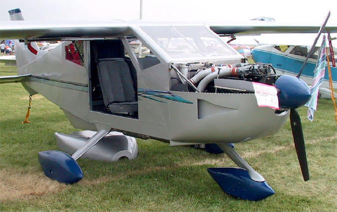
The plane is a BD-4, completed in May of 2000. The BD-4 was chosen because
it was easy to build, relatively inexpensive, carries four people, and is
relatively fast. Never satisfied with the status quo, significant modifications
were incorporated to accomplish specific objectives. The wings were lengthened
twenty-two inches per side, the flap length increased by the same amount, and
the flap deflection increased from 30 to 40 degrees, all to reduce the stall
speed. The wing was changed from the original fiberglass wing panels to aluminum
in an effort to reduce the fuel leakage problem frequently experienced with the
fiberglass panels. Rudder trim was added, and both stabilator and rudder trim
are driven by small, industrial, DC gear motors controlled by a small electrical
joystick located between the front seats. The doors were modified to hinge from
the top rather than the front, and were supported with gas springs. The
objective was to enable opening the doors in flight for better photography. It
also significantly improves cabin cooling while on the ground on hot days.
ENGINE
An automotive
engine was chosen because I could not rationalize the value of a conventional
aircraft engine, and I enjoy a technical challenge. This engine satisfied both
of these issues.
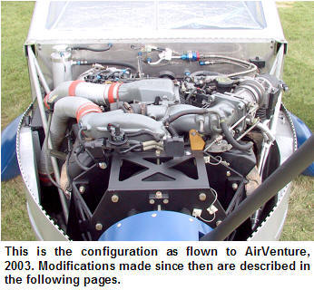
The engine is a 90-degree, 3.8-liter V-6 from a 1990
Thunderbird Super Coupe. It is supercharged by an Eaton blower and intercooled.
The compression ratio is 8.2: 1 and the fuel is supplied by six fuel injectors.
The engine is rated at 210 hp at 4000 rpm and delivers 315 lb-ft of torque at
just 2600 rpm.
Among other essentials such as a
Northwest Aero Products 1.7:1 ratio cog belted propeller speed reduction unit
(PSRU), this automobile engine conversion includes the standard automotive
sensors, multi-port fuel injection system, and computer ignition systems, less
the standard emissions junk. An emissions air pump (not standard in the car) was
added to serve as a vacuum source for the flight instruments.
|
|
|
The philosophy used to convert the
engine for aircraft use was - don’t change anything unless absolutely necessary.
Lacking automotive engineering credentials, the safest tactic was to keep
the conversion as simple as possible. There was no reasonable way to improve on the thousands
of engineering hours that Ford invested in the development of this engine.
However, some external adaptations were required to match the engine to the
airplane.
|
COOLING SYSTEM
A thorough study of available
data on water-cooled aircraft engines was completed and data from the most
successful installations was used for guidance. The data indicated the design
targets for the active frontal area of the radiator should be one square inch
per horsepower, and the radiator volume should be 2.52 cubic inches per
horsepower.
A radiator shop in Indianapolis was used to
fabricate the custom design based on the design targets. Assuming the engine
would produce the factory rated horsepower, the radiator was to be 23.5 inches
wide, 9 inches tall and 2.5 inches thick. There are small tanks on each end with
1.25” hose connections, a small drain valve in a lower corner, and a flange on
the upper surface to mount it to the airplane. The radiator is riveted directly
to the fuselage, perpendicular to the air stream. The radiator is connected to
the engine by 1.25” thin wall aluminum tubes running from the firewall to the
belly scoop under the fuselage. These are enclosed in a small tunnel for drag
reduction and appearance.
The belly-scoop, made from foam and fiberglass,
slips over the radiator from below and is fastened to the fuselage with four
bolts in the corners. Guidance from NACA publications dealing with inlet and
outlet configurations used in warbirds was used for the belly-scoop design.
When the shop completed the radiator, I found it to
be much thinner than I had requested. Instead of the specified 2.5 inches thick,
it was only 1.2 inches. Based on his experience with auto racing, the shop owner
believed it would be sufficient. So I mounted it and flight-testing has proven
that he was basically correct. However, there have been times on hot days,
during long climb outs, that the thicker radiator may have been beneficial.
EARLY DEVELOPMENT ISSUES
One of the early issues with the engine was an
intermittent misfire that occurred sporadically during full power climb-outs.
After eliminating every other possibility, I removed the fancy, high
performance, spiral core spark-plug wires that were advertised to be far
superior to the OEM equipment, and replaced them with OEM resistive wires. The
misfire problem was fixed. I did not say solved, because the actual underlying
cause is not understood. It may have been an impedance mismatch with the high
voltage coils. This is one of the areas where straying from the “don’t change
anything unless absolutely necessary” rule generated an unnecessary problem.
FUEL FLOW
For the first 100 hours or so, the plane was burning
about 13.5 gallons per hour in cruise, and the exhaust was very sooty. The
primary contributor is the OEM computer programming that adopts a
wide-open-throttle (W.O.T.) algorithm when certain operating parameters are met.
In the W.O.T. mode, the computer stops looking at the oxygen sensors to
determine how to adjust the fuel injection duty cycle and switches to an open
loop mode, using a look-up table that injects a predetermined amount of fuel
based on data from the mass airflow sensor (MAF). To protect the engine, this is
designed to be a rich mixture. Unfortunately, the computer defaults to this mode
for any power setting greater than that required for minimum cruise.
|
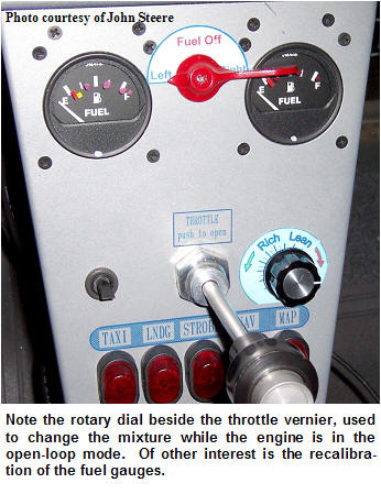
To overcome this problem, a passive voltage divider
circuit was designed and placed between the mass airflow sensor and the
computer. (See diagram.) This circuit supplies an adjustable percentage of
the signal from the MAF to the computer. This causes the computer to think the
engine is taking in less air than it actually is, so the computer tells the
injectors to deliver less fuel. The manually adjustable potentiometer is
positioned next to the throttle, allowing the mixture to be adjusted in flight.
The potentiometer is the only component in the circuit that has any significant
potential for failure. Its likely failure mode is to electrically open rather
than short out, so it’s positioned in the circuit where a failure
will cause the mixture to go rich if it opens, - a safe condition.
|
|
| |
|
On this water-cooled engine the EGT does not peak
then noticeably drop off as the mixture is leaned. The leaning procedure that
seems to work best is to slowly lean until the engine starts to run rough, then
enrich the mixture until it runs smoothly. This yields a 65-70% cruise fuel burn
rate of 10.5 to 11 gallons per hour of premium auto fuel. It has not been
necessary to enrich the mixture at low power settings, for starting, or ground
operations. During low power settings, the computer returns to the closed loop
mode and operates smoothly.
INDUCTION CHANGE
The original induction
system was a simplified version of what was supplied in the car. Due to size
constraints, the original ducting and resonator (shown right) were eliminated
and replaced with a flexible tube that carried induction air from a T-Bird air
filter directly to the MAF sensor. The air filter was positioned in a plenum
immediately behind a NACA flush inlet on the left side of the cowling.
This system worked OK, but took up a lot of space,
and I was concerned that the air filter might soften and collapse into its
plenum if the plane was flown through a heavy rainstorm. The air filter location
was also the only practical place to mount a larger oil cooler that was needed
to extend the time between oil changes.
|
|
| |
|
|
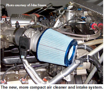
In late 2003, the decision was made to reconfigure
the induction and oil cooler systems to get them off the worry list. At Auto
Zone, a simple well-constructed cone filter was found with an exit flange that
fit perfectly into the inlet of the mass airflow sensor. (See photo to the
right) The opposite end of the cone filter is supported by an |
|
aluminum bracket attached to
the engine mount by an Adel clamp. This all fits neatly under the cowling and
ends the concern about a wet filter collapsing and choking the induction system.
I may be paying an imperceptivity small power penalty since the induction air
drawn from under the cowling is warmer than air sourced through the original
NACA flush inlet.
The original oil cooler was a small, single loop,
unit set in the NACA inlet plenum on the right side of the plane, immediately in
front of the intercooler. With the NACA flush vent on the left side now
available, the eleven-inch square plenum was filled with an automotive oil
cooler. The effect on oil temperature was very gratifying. With both
measurements taken on 70° F days, the oil temperature dropped from 232° to
210°. With the new oil cooler now taking on a larger share of the overall
cooling load, the water |
|
|
temp. dropped from 227° to 220° F. Very satisfying
results for an amateur. |
|
EXHAUST SYSTEM
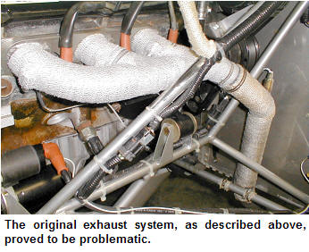
The exhaust system has been the most troublesome aspect of the engine
conversion. The original headers were fabricated from mild steel tubing as a
cost savings choice. Bad decision! Because the original header design brought
them within ¾” of the sparkplugs, they had to be insulated with an exhaust wrap
to protect the sparkplug |
|
 |
boots.
The insulation was very effective, but did not last long. Within ten hours it
lost its flexibility, and if you inadvertently touched it while working on
something nearby, it would fracture and break off. The more serious matter was
the higher manifold temperature caused by the insulation. With any cooling air
to the header effectively blocked by the insulation, the mild steel overheated
and finger sized holes developed in both headers within twenty hours.
New exhaust headers in the same general
configuration (mistake #2) were fabricated from 321 stainless. I inadvertently
ordered the bends with a larger radius (mistake #3) than used with the mild
steel header, resulting in the tube passing within ½” of the plugs.
|
|
 |
The
stainless tubing held up to the heat. But even with the insulating wrap, a
sparkplug boot would occasionally break down, allowing an arc to occur between
the sparkplug and the header. This happened one time while my wife was on board,
leading to an emotional reaction to the sudden engine roughness, and a
significantly reduced confidence in the airplane. These events were not life
threatening since the airplane could still climb very well on five cylinders.
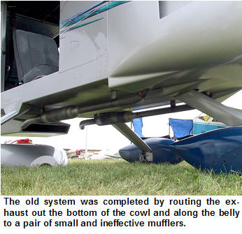
After several “five-cylinder” events, I decided to
redesign the entire exhaust system. The new design had to provide as much
clearance from the sparkplugs as possible, eliminate the need for insulation
wrap, and make accommodation for the under-engine muffler I wanted to add.
The original header design brought the header
straight back towards the firewall (see first photo |
|
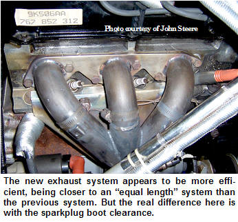
in the series at the left) before dropping down to
exit just ahead of the firewall. The new design drops immediately from each
exhaust port, with the three tubes joining approximately 8 inches below the
ports. This |
 |
significantly improves the clearance from the sparkplugs and
provides a more direct route towards the bottom of the cowling. Below the “Y”
connection, the tubing diameter changes from 1-3/4” to 2”, and the oxygen sensor
mounts just below the “Y”. The 2” tube continues down to a ball joint, then
terminates with a V-Band clamp that enables removal of the exhaust pipes or
muffler without removing the headers.
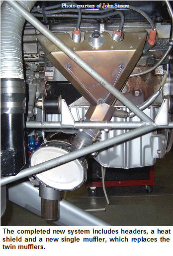
The exhaust manifolds are enclosed in a thin
(0.025”) stainless steel heat shield to prevent excessive radiant heating of
adjacent components. (See photo at right). The heat shields include 1” air duct
couplings where outside air is introduced to provide in-flight manifold cooling.
The sparkplug boots are also enclosed in protective sleeves because they are
still too close to those glowing header pipes. This header arrangement has
worked well since its installation about 40 hours ago, eliminating those
annoying “five cylinder” events.
This system was flown for about 38 hours with
straight pipes plus a crossover tube attached to the V-Band clamps. This system
performed very well, but the noise made communication in the cockpit, even with
an intercom and good, noise-canceling, headsets very difficult. The neighbors (I
live in a fly-in community) also said that the noise made the trees rattle
during take off.
|
MUFFLER
For both of the previously stated reasons, a muffler was in order. Due to
the tight cowling and cramped quarters under the engine, a suitable
off-the-shelf muffler that would physically fit could not be found. So, I
designed a muffler that would fit the available space, and hopefully provide enough internal baffling to
reduce |
|
the noise without causing too much back pressure. Since I am not a muffler engineer, some elementary
research was required. An Internet search disclosed that there are five basic
principles available for use in passive mufflers – reflection, absorption,
restriction, expansion, resonance, and combinations of these. Space constraints
limited options for this application primarily to the restriction realm.
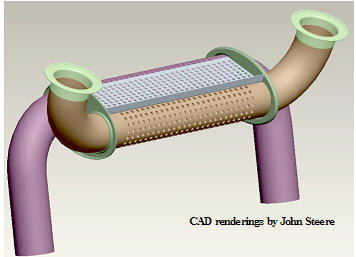
The muffler consists of two “U” shaped tubes, two
baffle plates, two end caps, and an outer skin. The tubes are 16 gauge, 321
stainless, and the baffles, ends, and wrap are 0.025” thick 304 stainless, all
welded together with 308 stainless filler rod. The end caps were shaped using
wooden form blocks for the perimeter, and simple turned steel
mandrels to form the holes for the tubing. The tubes are preformed 90° bends
welded end-to-end in the center of the muffler.
|
|
|
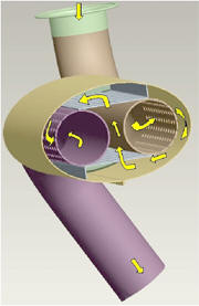
The exhaust gasses enter from both ends of the
flanged exhaust pipe, exit the pipe through a series of ¼” holes along the
forward surface, then travel downward (because they are blocked by a bent-up tab
on the upper baffle.) They then pass through the lower baffle, between the two
pipes, through the upper baffle, through perforations into the tail pipe, and
out the ends of the tail pipes to the atmosphere. Each set of perforations has
about twice
|
|
 |
the open cross-sectional area of the tubes.
The entire muffler is enclosed in a stainless steel
heat shield (not shown), including the exhaust pipes, until they exit the lower
cowling. Cooling air is introduced between the heat shield and muffler by way of
a 2” air duct. The cooling air is exhausted between the tail pipes and
their heat shields. This cooling air is not used for cabin heat as there s a
welded joint running the length of the muffler skin, and there is
another, safe source for cabin heat.
The effect of the muffler was immediately apparent
when the engine was started after installation. The noise in the cockpit was
|
|
significantly reduced to the point that intercom communication was possible
without turning on the noise canceling in the earphones. That’s not to say that
I wouldn’t like it quieter, but the noise has dropped from oppressive to
operationally reasonable in the cockpit.
|
|
The effect on power has yet to be fully analyzed,
but does not seem to be significant. Supercharger boost pressure during takeoff
has increased from 9 PSI to 11-PSI, and at cruise RPM (2400,) the pressure
increased from 2-PSI to 3-PSI. With all else remaining the same, boost pressure
is related to back pressure in the exhaust system. The 11-PSI full throttle
boost is still less than the 12 to 14-PSI normally seen in the 1990 T-Bird Super
coupe from which this engine was removed.
CABIN HEAT
I am not comfortable using the exhaust system as a
cabin heat source unless the heat muff could be mounted over an area free of
welded joints. The new, compact, exhaust system doesn’t offer that choice. Water
cooled engines also provide the option of using a small automotive heater core
as a safe heat source, but require additional plumbing, add some weight, and
take up space for the heater core and a circulation fan. With the engine
compartment and both sides of the firewall rather crowded, the heater core was
not a good option. Fortunately, |
 |
|
there is another source for
safe, warm air from a super charged engine – the intercooler. Cooling air for
the intercooler enters through a flush NACA inlet on the right side of the
airplane and passes through the intercooler, into an exhaust duct that directs
the warmed air out the bottom of the cowling, just ahead of the firewall. A
two-inch air duct flange through the firewall, coupled into the
intercooler exhaust duct, captures part of the warmed air and delivers it to the
cockpit through a butterfly valve. The intercooler only provides warm air when
the supercharger is actually pressurizing the induction air, so there is no heat
while on the ground. Since this system is pressurized by outside air through the
NACA inlet on the side of the cowling, there is no risk of carbon monoxide
poisoning. |
FUEL GAUGE CALIBRATION
I learned a very important lesson a couple years
ago, while on a return flight from Western Michigan to my home base, Twelve Oaks
Airport, Martinsville, Indiana (II87), about 16 nautical miles South of
Indianapolis. Shortly after passing Indianapolis Metropolitan airport, the
engine quit. A quick scan of the fuel gauges indicated about six gallons
remaining in the left tank, (the tank from which the engine was drawing fuel),
and about ten gallons in the right tank. I immediately switched tanks, turned on
the second fuel pump, and said a quick but urgent prayer. I then remembered that
Metro airport had just passed under my right wing, made a quick right turn, and
found myself perfectly set up on downwind for runway one-five.
I continued looking for the source of the problem on
down-wind, believing it to be fuel related due to the way the engine died - a
smooth RPM reduction over a period of about three seconds. But I had very
carefully calibrated the fuel gauges while building the airplane, and had marked
the gauges at several points with the actual fuel level, and the gauge still
showed six gallons. As I turned onto a short final, with the prop windmilling,
the engine restarted on its own. I landed and taxied to the ramp, with
everything performing normally. A visual check of the left wing tank found it
completely dry.
After thinking about this for a few minutes, it
dawned on me that the procedure used for calibrating the fuel gauges was faulty.
The gauges were calibrated while the plane was still in the basement, with the
plane on battery power - about twelve volts. In flight, with the alternator
charging, the electrical bus is carrying about fourteen volts. That two-volt
difference caused the gauge to read six gallons higher on the low end of the
scale. Needless to say, the fuel gauges were recalibrated with the engine
running.
NOSE WHEEL
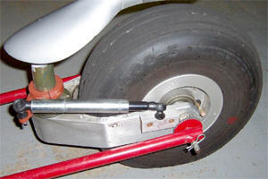
The
BD-4 uses a castering nose wheel with a spring-loaded friction pad around the
spindle to prevent nose wheel shimmy. Early in the flight-testing, the spring
pressure was reduced because the brakes were wearing rapidly as I fought the
nose wheel during mile long ground excursions. Unfortunately, the reduced
friction allowed the nose wheel to shimmy aggressively. After fighting the
friction adjustment battle and other unsuccessful mechanisms for three years,
and destroying two nose wheel pants, the decision was made to add a hydraulic
damper. Not wanting to pay the ridiculous cost of an aircraft damper, a search
for alternatives was in order. An Internet search led to a self-centering damper
that in normal life is used to control hydrostatic transmissions, typically
linked to a control lever or pedal to provide a controlled rate of actuation.
This little unit cost less than $50, and has eliminated the shimmy problem. Now, a new wheel pant is in order.
For additional information about this plane, go to:
www.bd-4.org/builderlist_sheet.php?session=&id=42&user=John%20Steere
CONCLUSION
I stated in the first report on this plane, “I could
not rationalize the cost of a new or used 180-200 hp Lycoming engine (that the
airplane was originally designed to use) against my perception of the value of
the engine.”
To put things in perspective, I saw an advertisement
in a recent aviation periodical for a 180-hp. fuel injected aircraft engine with
FADC controls for $29,900. The Thunderbird installation, including the PSRU,
alternator, air pump, supercharger, fuel injection, computer control system, and
all the sensors and other incidentals needed to complete the system, cost
approximately $7,000. I think that is a pretty good value for a new engine with
21st century controls, rated at 210 hp.
All of that is still true, and based on the 185
hours of experience with this engine, I would choose an automotive engine again.
Hmm…. that Corvette LS1 engine looks interesting!
Comment on this article:
|